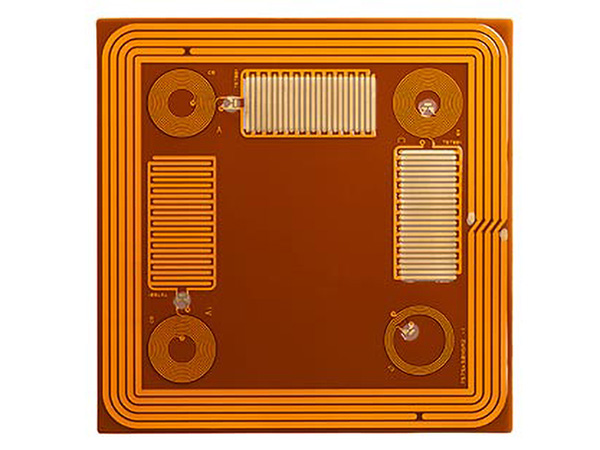
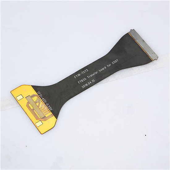
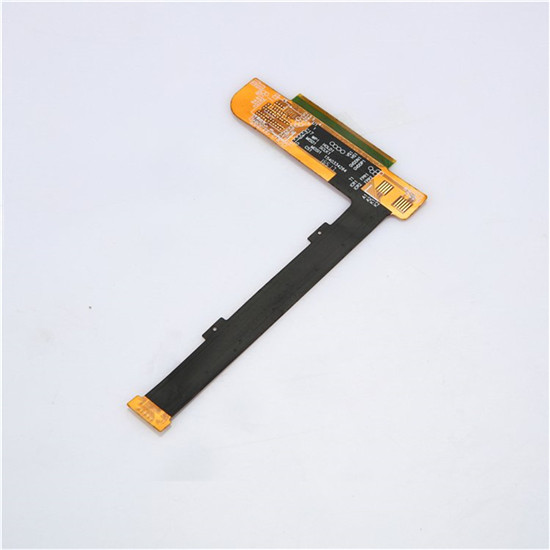
Flexible PCB is mainly divided into single-sided flex PCB, hollow FPCB board, double-sided Flex PCB, multi-layer flexible board, and rigid-flexible PCB board.
Rayming provide 1- 12 Layer Flexible PCB Manufacturing services for both quick turn prototypes and production quantities. Flexible circuit fabrication and assembly, Our Engineer provide free DFM Checking.
Flexible circuits provide excellent electrical performance, meet the design needs of smaller and higher-density mounting, and reduce assembly processes and enhance reliability. Flexible circuit boards are the only solution to meet the miniaturization and mobility requirements of electronic products. It can be bent, wound, folded freely, and can withstand millions of dynamic bending without damaging the wire.
It can be arranged arbitrarily according to the space layout requirements. It can also be moved and stretched arbitrarily in three-dimensional space to integrate component assembly and wire connection. The flexible circuit board can significantly reduce the volume and weight of electronic products. Furthermore, it is suitable for developing electronic products in high density, miniaturization, and high reliability.
Features of Flexible Circuit PCB
· Short: Short assembly time (Reduce 30% hand wiring), All lines are configured, eliminating the need to connect redundant cables.
· Small: smaller than PCB (Rigid board), It can effectively reduce the product volume and increase the convenience of carrying.
· Light: Lighter than rigid PCB, Can reduce the weight of the final product.
· Thin: Thickness is thinner than rigid PCB, It can improve the softness and strengthen the three-dimensional assembly in a limited space.
What are the advantages of flexible PCB?
Flexible PCB is printed circuits made of flexible insulating substrates and have many advantages over rigid PCB:
1. Flexible PCB can be bent, wound, and folded freely. Itcan be arranged according to the space layout requirements. Itcan also be moved and expanded in three-dimensional space, which allows us to achieve the integration of component assembly and wire connection.
2.The use of FPC can greatly reduce the volumeand weight of electronic products(up to 70% saving). It is suitable for the development of electronic products in the direction of high density, miniaturization, and high reliability. Therefore, FPC has been widely used in aerospace, military, mobile communications, laptops, computer peripherals, PDAs, digital cameras, and other fields or products.
3.FPC also has the advantages of good heat dissipation and solderability, easy assembly and low overall cost, etc. The soft and hard combination design also makes up for the slight deficiency of the flexible substrate in the component carrying capacity to a certain extent.
4.Wiring errors eliminated.
5.Improves electronic packaging – Gives designers the ability to solve packaging and interconnect issues based on the ability to form, bend, and move.
6.Interconnect solution – Reduces the number of interconnects (wire, cables, connectors, PCBs).
7.Electrical integration – Tailored solutions can be created based on the myriad of material choices, plating, and designs.
Disadvantages of Flexible PCB
1. High one-time initial cost: Since the flexible PCB is designed and manufactured for special applications.The initial circuit design, wiring,and photographic masters require higher costs. Unless there is a particular need to apply a flexible PCB, it is usually best not to use it in a small amount of application.
2. It is difficult to change and repair the flexible PCB: Once the flexible PCB is created, it must be modified from the original design or the light drawing program. The surface is covered with a protective film, which must be removed before repair and restored after repair. Due to the above, it is a relatively difficult task.
3. Size is restricted: Flexible PCBs are usually manufactured by a batch method when they are not commonin the industry. This is why they cannot be made very long and wide due to the limitation of the size of production equipment.
4. Improper operation and easy damage: Improper installationand operationcan cause damage to the flexible circuit. As a result, its soldering and rework need to be operated by trained personnel.
Main Raw Materials of FPC
The main raw materials include: 1. base materials, 2. cover film, 3. reinforcement, 4. other auxiliary materials.
1) Substrate
1.1 Adhesive substrate
Adhesive substrates are mainly composed of three parts: copper foil, adhesive, and PI. There are two types of single-sided substrates and double-sided substrates. The material with only one side of copper foil is a single-sided substrate, and the material with double-sided copper foil is a double-sided substrate.
1.2 Adhesive-free substrate
The non-adhesive substrate is the substrate without the adhesive layer. Compared with the ordinary adhesive substrate, the middle adhesive layer is missing and composed of copper foil and PI. Thus, the non-adhesive substrate is thinner than the adhesive substrate. It also has other advantages, such as better dimensional stability, higher heat resistance, higher bending resistance, and better chemical resistance. Currently, it has been widely used.
Copper foil: At present, the commonly used copper foil thickness has the following specifications, 1 oz, 1/2 oz, 1/3 oz. A thinner copper foil with a thickness of 1/4 oz is also on the market. However, this kind of material is currently used in China and makes ultra-circuit (line width and line spacing are 0.05 mm and below) products. With the increasing requirements of customers, materials of this specification will be widely used in the future.
2) Cover film
It is mainly composed of three parts: release paper, glue, and PI. In the end, only the glue and PI remain on the product. The release paper will be torn off during the production process and will not be used again (its role is to protect the glue from foreign matters)
3) Flexible PCB Stiffener
The stiffener is a specific material used for FPC. It is used in a specific part of the product to increase the support strength to enhance the “soft” characteristic of FPC.
1. FR4 stiffener: The main components are glass fiber cloth and epoxy resin glue, which are the same as the FR4 material used in PCB.
2. Steel sheet stiffener: The composition is steel, which has strong hardness and support strength.
3. PI stiffener: The same as the cover film, consisting of PI and release paper. However, the PI layer is thicker, and it can be produced from 2 MIL to 9 MIL.
4) Other auxiliary materials
1. Pure glue: This adhesive film is a heat-curing acrylic adhesive film composed of protective paper/release film and a glue layer. It is mainly used for layered boards, rigid and flexible boards, and FR-4/Steel sheet reinforcement board, which plays a role in bonding.
2. Electromagnetic protective film: Paste on the board surface for shielding.
3. Pure copper foil: Only composed of copper foil, mainly used for hollow board production.
6 Types of FPC
FPC types have the following six distinctions:
1. Single flex PCB: Only one side has circuits.
2. Double-sided flex PCB
3. Hollow board: Also known as window board (opening on the finger surface).
4. Layered board: Two-sided circuit (separate).
5. Multilayer flex PCB
6. Rigid-flexible PCB board: Acombination of flex board and rigid board
Design Analysis of Flexible PCB
The structural design of the flex PCB is also critical. As some PCB designers do not know enough about the characteristics of flex PCB, the FPC designed is prone to stress concentration problems, which may cause the problem of FPC circuit breakage.
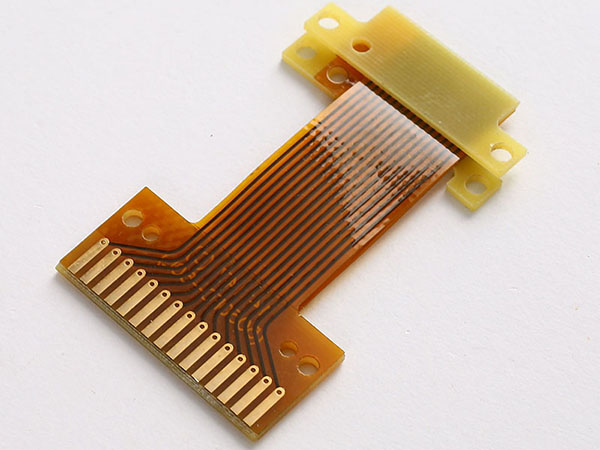
The left FPC design diagram below shows the cover film’s endpoints on the upper and lower sides are designed on the same cross-section. The double-sided adhesive also ends at the same point, which will form a stress-concentrated cross-section. The edge of the insulating layer (cover film, Polymide) of the cable, as shown on the right side of the figure, staggered 1.0 mm to avoid stress concentration and breaking of the flexible cable. However, pay attention to whether the underside of the 1.0mm FPCB solder pads are still pressed on the PCB solder pads. Avoid short-circuit with test points or vias nearby.
Let’s look at another illustration. The designer sets the HotBar flexible PCB on the edge of the board. The diagram on the left shows the original design. The soldering pad of the HotBar flex PCB falls on the edge of the PCB. However, after production, we’ve noticed a common occurrence of flex PCB fracture, which is concentrated at the edge of the protective insulating layer (cover film). After further analysis, it is found that there is a stress concentration point at the edge of the PCB and the edge of the insulating layer of the flexible PCB.
Firstly, to improve the stress concentration point, the strategy is to move the soldering pad of the soft board inside the PCB slightly. Secondly, add double-sided tape, and extend the insulating layer of the soft board forward to cover the stress concentration point of Yuanlai. In this way, not only the strength of the soft plate is strengthened, but the original stress concentration point is also eliminated. After the modifications were applied, the problem of the flexible PCB fracture is not detectable.
How do you make a PCB flexible?
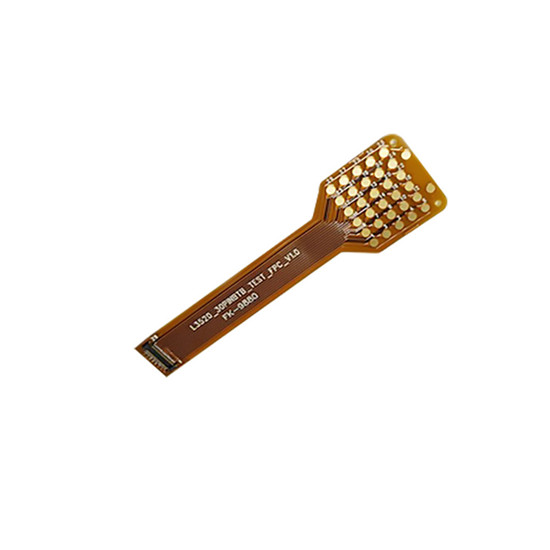
The flexible circuit board is highly reliable and made of polyimide or polyester film as the base material. Referred to as a soft board or FPC, it has high wiring density, lightweight, and thin thickness.
Pre-production treatment
There must be a complete and qualified production process to make a good-quality flex PCB. From pre-processing before production to final shipment, every procedure must be strictly implemented. In the production process, in order to prevent excessive open and short circuits from causing low yield or reduce the problem of Flex PCB scrap and replenishment caused by process problems such as drilling, calendering, and cutting, and to evaluate how to select materials to achieve customer use The best effect flexible circuit board. Pre-production treatment is vital.
Before production, in pre-processing, three aspects need to be processed and complete by engineers. The first is the flexible PCB engineering evaluation, mainly to evaluate whether the customer’s FPC board can be produced. Secondly, the engineers will review the company’s production capacity to see if it can meet the customer’s technical and pricing requirements. If the engineering evaluation passes, then materials preparation will begin immediately to meet the production process. Finally, the engineer processes the customer’s CAD structure drawing, Gerber data, and other engineering documents to suit the production environment and specifications of the equipment. Then regular production process continues by the delegation of production drawings and MI (engineering process card) to the production department, document control, purchasing, and other departments.
1) Manufacturing Process of Double-Sided Flex PCB
Cutting → Drilling → PTH → Plating → Pre-treatment → Pasting Dry Film → Alignment → Exposure → Development → Graphic Plating → Stripping → Pretreatment → Pasting Dry Film → Alignment Exposure → Development → Etching → Stripping → Surface Treatment → Paste the cover film → Pressing → Curing → Immersion of nickel gold → Printing characters → Shearing → Electrical test → Laser profile or Punching → Final inspection → Packaging → Shipment
2) Manufacturing Process of Single-Sided Flex PCB
Cutting → Drilling → Pasting Dry Film → Alignment → Exposure → Developing → Etching → Stripping → Surface Treatment → Covering Film → Pressing → Curing → Surface Treatment → Immersion Nickel Gold → Printing Characters → Cutting → Electrical Measurement → Laser profile or Punching → Final Inspection → Packaging → Shipment
3) Process Characteristics of Flexible PCB
1. Surface treatment: Immersion gold, OSP, Gold plating, HASL/LF
2. Profile: Manual shape, CNC (numerical control machine) cutting, Laser cutting
3. Substrate copper thickness: 1/3 ounce, 1/2 ounce, 1 ounce, 2 ounces, 4 ounces
4) Detector
The characteristics of the material of the flexible circuit board have a wide range of applications. To more effectively reduce the volume and achieve a certain degree of accuracy, the characteristics of the three-dimensional space and the thin thickness are better applied to digital products, mobile phones, and notebook computers. The instrument used for flexible circuit board (FPC) testing is an optical image measuring instrument.
What are flexible circuits used for?
The characteristics of the material of the flexible circuit board have a wide range of applications. To more effectively reduce the volume and achieve a certain degree of accuracy, the characteristics of the three-dimensional space and the thin thickness are better applied to digital products, mobile phones, and notebook computers. The instrument used for flexible circuit board (FPC) testing is an optical image measuring instrument.
Communications
Consumer Electronics
Automotive
Medical
Industrial
Aerospace
Military
Transportation
RayMing is an experienced flex PCB manufacturer, able to handle up to 12 layer flex PCB manufacturing and different stiffer requirements (PI, FR4, Aluminum).
5 Differences between Rigid PCB with Flex PCB
Rigid PCB : Rigid Printed Circuit Board Flex PCB : Flexible Circuits
AWhat is The rigid circuit boards? What is the flexible circuits? What is the difference between the two?
Flexible PCB Also known as flexible circuit boards,Is rolled with copper or Electrolytic copper as the material,Flexibility is very good, Bending resistance.
Normally we talk about PCB Called rigid board,
The FPC called the Flexible PCB.Small and medium-sized flexible circuits/s design follows Rigid circuit board design,
But not completely The same with rigid circuit board.Specific differences can be summarized as the following aspects:
1. softness
A standard for flexible circuit boards Is to require good flexibility,
Flexible printed circuit board Three-dimensional space is very important,Because of bending and flexible applications
Can save space and reduce the board layer,Mostly single-sided.Hard board material is Requirements more excellent,
With compression,Wear-resistant high temperature and other characteristics,So the limitations of the space,Common Multilayer PCB.
2. the carrying capacity of the line
Compared with the rigid circuit board,Flexible PCB is Poor,Anything from a straight line to a corner Or different line width changes,Should be smooth transition.We can see a lot Flex PCB with snake-like alignment. The same line width from the hard board Of the current carrying capacity
Much stronger than the soft board,So we common
Flexible PCB applications ,In the place of smaller current,Such as mobile phone cable.
3. the pad design
In the periphery of the pad,There is one from the flexible material Rigid material changes.Board This area is the soft board
More likely to damage the conductor.Therefore, the pads should be avoided In the region prone to bending.Rigid board does not need to emphasize this problem.
4. the shape of the plate
Regardless of the soft board hard board
Shape will be a variety of,
Flexible PCB in shape On the general preferred rectangle,So you can better save the substrate,Leave at the edge of the board
Enough free margins, In the shape,
General solution made of circular
Than the sharp inner angle is better,
The inner solution of the light shape is easy
Causing the plate to tear.
Rigid board is a fixed mode,
Depending on the shape of the product.
5. the thickness of the board
FPC is thinner than Rigid board,
Conventional hard board thinnest to do
To 0.2mm has been very good,
While the flexible pcb Can be thinner than paper,
So in many areas or
There is a good space for development.
From the above can see the Flex PCB
And Rigid boards are different,
Each have their own fields.